Cable Tray Support Distance
Cable Tray is used to support large number of cable or tubing between two points. Distance between fixing points and cable tray support spacing shall be a maximum of three meter for ladder type tray and two meter maximum for perforated tray so as to avoid strain on cable trays.

Cable Tray Installation Details Page 1 Line 17qq Com
Large retail and warehouse installations use cable tray to support their data communication cable systems.

Cable tray support distance
. From walls or vertical columns with shelf or cantilevered brackets Typical Detail For Cable Tray Installation And. The NEMA classes are based on cable loads of 50 75 and 100 per lineal foot. Nuclear power plant safety-related cable tray support systems subjected to seismic loadings were originally understood and designed to.0121 270 8507 Email. Hold-down clips and support fitting shall be provided at each support point. 2006 with a minimum coating weight of 275gm².
Distance between each Cable is 10mm. Cable Tray should be perforated and 20 spare Capacity. NEMA FG-1 was rescinded as a published standard in November 2017.
This is the total weight of cables in the tray. Tray may refers to cable tray or tubing tray. In most UK steel construction the allowable deflection at safe working load is L200 for beams and L180 for cantilevers based on UK steel design standards.
Cable tray and cable fittings shall be fully perforated slot sizes shall be 20mm x 7mm or similar running parallel to the length of the cable tray and 135mm by 11mm or similar running perpendicular to the length of the cable tray and shall be. Cable trays shall be supported by mild steel galvanized brackets at regular intervals of 12mm maximum and at 255mm from bends and tees. Support of cable tray shall be located within 2ft 600mm max of each side of expansion splice plates.
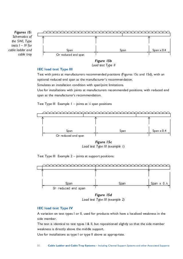
Support Spans--Support span is the distance between the supports. A Light Duty Non-Return Flange. Support Load Calculation Per IEC 61537.
The Support Span should not be greater than the straight section length. For purposes of selecting a suitable tray this weight should be rounded off to the next higher NEMA working allowable load. The distance between each support is the support spanYou can support your cable tray system.
1 2 Nos of 35Cx300 Sqmm XLPE Cable having 597mm Outer Diameter and 59 KgMeter weight. A support should be located 2 Ft. One or more spans IEC 61537 73i For installations with more than one span it is important to notice that the loading capacity is not the same form one end to the other.
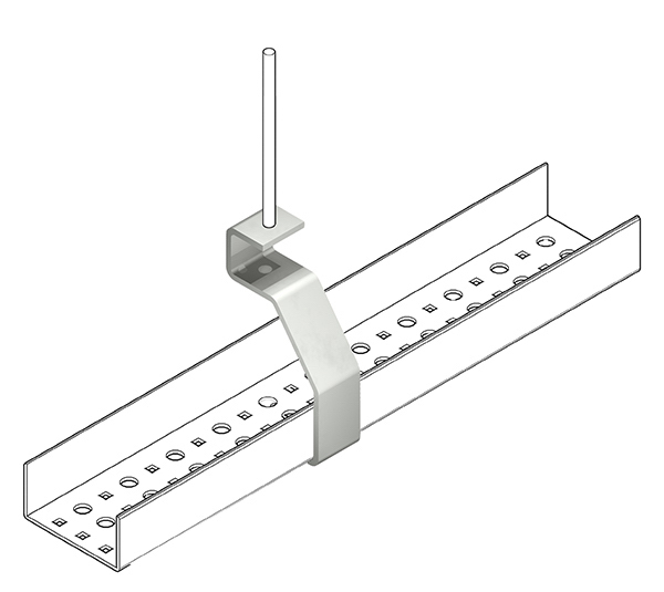
Below drawing shows how to install cable tray and its support system. The National Electrical Manufacturers Association NEMA has standardized the classification of cable tray based on the load to be carried per foot and the distance between span supports. Support points are often trapezes suspended from threaded rod.
It would be impossible to have the wiring system flexibility they need with a conduit wiring system. Deflection limits are usually expressed as a proportion of the support span L or the product width W. Cable are laying in Single Layer in Cable Tray.
Expansion guides should be used at each support point except where the tray is hung with rods. 2000 and BS EN 10143. The load per foot should include not only the cable but additional load factors for wind snow ice etc.
Vertical straight lengths should be supported at intervals dictated by the building structure not to exceed 20 Ft. On each side of an expansion connection. Distance from pin support w is Load per unit length N.
Evenly Distributed Load 2 X Point Load Support Distance. Cable tray installation shall be designed to carry a load of 100kgm. SnapTrack tray standard 20 lengths.
FG 1 Fiberglass Cable Tray Systems Covers construction and test requirements for continuous complete nonmetallic systems of ladder ventilated solid bottom cable trays or channel type trays intended for the support of power or control cables or both. Cable Management and Support System Specialist Phone. The NEMA standard support spans are based on 8 12 16 and 20.
Make use of cable tray to support and route the large volumes of cable needed for their operations with a high degree of dependability. Mushroom-headed steel roofing bolts and nuts shall be used for the installation and coupling of trays. Several types of material are available such.
Tray material shall be selected according to environmental and installation conditions. In the case of electrical products such as cable tray or ladder which are load rated in kilograms per metre the span is the distance between support points separate from the overall length of the tray or ladder itself. Calculate Size of Cable Tray for Following Cable Schedule.

Cable Trays Nema Classifications Unistrut Service Co

Cable Tray Hanger Bracket Channel Hangers Techline Mfg

Cable Support Systems Design And Installation Ee Publishers

Cable Support Systems Design And Installation Ee Publishers
Cable Trays Size Calculator 1 0 Apk Androidappsapk Co

Beama Best Practice Guide To Cable Ladder Cable Tray Systems
Cable Trays Size Calculator 1 0 Apk Androidappsapk Co

Cable Tray Sizes Standard Page 1 Line 17qq Com

Practices For Grounding And Bonding Of Cable Trays Eep Cable Tray Cable Trays Cable

Beama Best Practice Guide To Cable Ladder Cable Tray Systems

Huaneng Telecom Co Ltd In China Produce And Export Preformed Line Products Fiber Optical Cable Accessories Cable Cable Tray Wire Clamp Fiber Optic Cable

Wire Mesh Cable Tray In 2020 Cable Tray Wire Mesh Cable

Arindam Bhadra Fire Safety Cable Tray Selection For Fire Cable
Cable Tray Safe Working Load Test Swl Electrical Safety

Macromolecule Alloy Cable Tray Chs

Economical Cable Trays From Wirerun Cable Tray Cable Trays Cable

Procedure For Instrument Branch Cable Tray Installation Paktechpoint


0 Response to "Cable Tray Support Distance"
Post a Comment