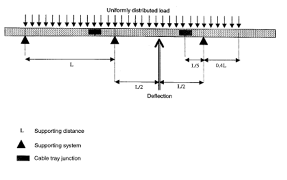
Cable Tray Support Span Distance
Q uniformly distributed load tested according to DIN EN IEC 61537 standard Long Span Cable Tray solid Weight per 100 672 kg 311200 EAN code model no. The load per foot should include not only the cable but additional load factors for wind snow ice etc.
Overview Of Support Systems For Cable And Equipment Cabling Installation Maintenance
But against horizontal forces it has to be fastened to the wall or column as per Figure 49C for instanceIn any case the weight of 20 ft length of all cables will be hung in this section will be over the limited force recommended by manufacturer.
Cable tray support span distance
. A support should be located 2 Ft. SnapTrack tray standard 20 lengths. Trays that meet NEMA specs support 3- 4.In most UK steel construction the allowable deflection at safe working load is L200 for beams and L180 for cantilevers based on UK steel design standards. It is shown that the optimal span suggested in this. The determination of spacing is based primarily by size and type of cable being supported.
Perforated Solid Cable Tray - Load Data Perforated Cable Tray Weights kgm Perforated Solid Bottom Cable Tray - Middle East Height Thickness Span Material Load kgm Material Load kgm 50 1036 335 75 15mm 3m Steel 1585 Aluminum 526 100 1829 734 Height Thickness Span Material Load kgm Material Load kgm 50 792 468. Channel Cable Tray provides. One or more spans IEC 61537 73i For installations with more than one span it is important to notice that the loading capacity is not the same form one end to the other.
It shall contain 50 lbsft of cables and support 15 lbsft of snow load. S WRU 105200 height H 10541 mmInch width B 20078 mmInch thick- ness t mmInch 15 delivery length m 6 m. It shall contain 50 lbsft of cables and support 15 lbsft of snow load.
Longer spans mean fewer supports which translates to lower installed costs. Deflection limits are usually expressed as a proportion of the support span L or the product width W. The National Electrical Manufacturers Association NEMA has standardized the classification of cable tray based on the load to be carried per foot and the distance between span supports.
The NEMA standard support spans are based on 8 12 16 and 20. The Support Span should not be greater than the straight section length. In many cases the higher your desired load the shorter the maximum allowable.
It is also required to support a 250 pound concentratedstaticloadappliedinthecenterofthetraywidth. Hold-down clips and support fitting shall be provided at each support point. Standard rung spacing is ventilated maximum opening of 52 mm 150 mm 225 mm and 300 mm.
This is the total weight of cables in the tray. Cable trays and accessories shall be electrically and mechanically continuous throughout their length. Evenly Distributed Load 2 X Point Load Support Distance.
Support of cable tray shall be located within 2ft 600mm max of each side of expansion splice plates. For Cable Tray Support span 20 Mtr. There are cable trays available to meet all NEMA requirements with spans of 8 12 16 or 20 feet and loading capacities of 50 75 or 100 lbsft.
In the case of electrical products such as cable tray or ladder which are load rated in kilograms per metre the span is the distance between support points separate from the overall length of the tray or ladder itself. Support Spans-- Support span is the distance between the supports. Also available in 3 meter length same price per meter Load Chart.
Support Load Calculation Per IEC 61537. If the steel cable tray is 6 inches depth 14 gauge hot-dip galvanized steel will be self standing. For purposes of selecting a suitable tray this weight should be rounded off to the next higher NEMA working allowable load.
Splice joints fall between the support and the quarter point. An economical support for cable drops and branch cable runs from the backbone cable tray system. Acable tray is to be supported on 20 spans.
It is also required to support a 250 pound concentratedstaticloadappliedinthecenterofthetraywidth. Cable Tray and Trunking joints are to be positioned as close to the supports as possible not more than 300 mm from either side. Acable tray is to be supported on 20 spans.
The constructability for the longer span obtained from finite element analysis has been validated in view of manual handling of the cable tray. When installing a 12-foot long section for example a support spacing of 37 m 12 foot causes the splice joints to fall at the same position every time. The distance measured from center of rung to center of adjacent rung.
Cable tray to support the static weight of cables. It is equivalent to destructive load capacity with minimum safety factor of 15 SumiP Sumip FRP Cable Tray System Widht of Type of Tray Load Kg Mtr. On each side of an expansion connection.
150 mm SLC 3 30 300 mm SLC 3 60 450 mm SLC 3 75 600 mm SLC 4 90 750 mm SLC 4 120 900 mm SLC 5 150. Support points are often trapezes suspended from threaded rod cantilever brackets or other strut systems. Trough cable tray is generally used for moderate heat generating applications with short to intermediate support spans of 5 feet to 12 feet.
Vertical straight lengths should be supported at intervals dictated by the building structure not to exceed 20 Ft. Connection and splices between horizontal sections of tray should fall at the quarter point of the span. The entire cable tray system shall be bonded and 12 mm x 25 mm tinned copper links shall be bolted across each joint in the system by means.
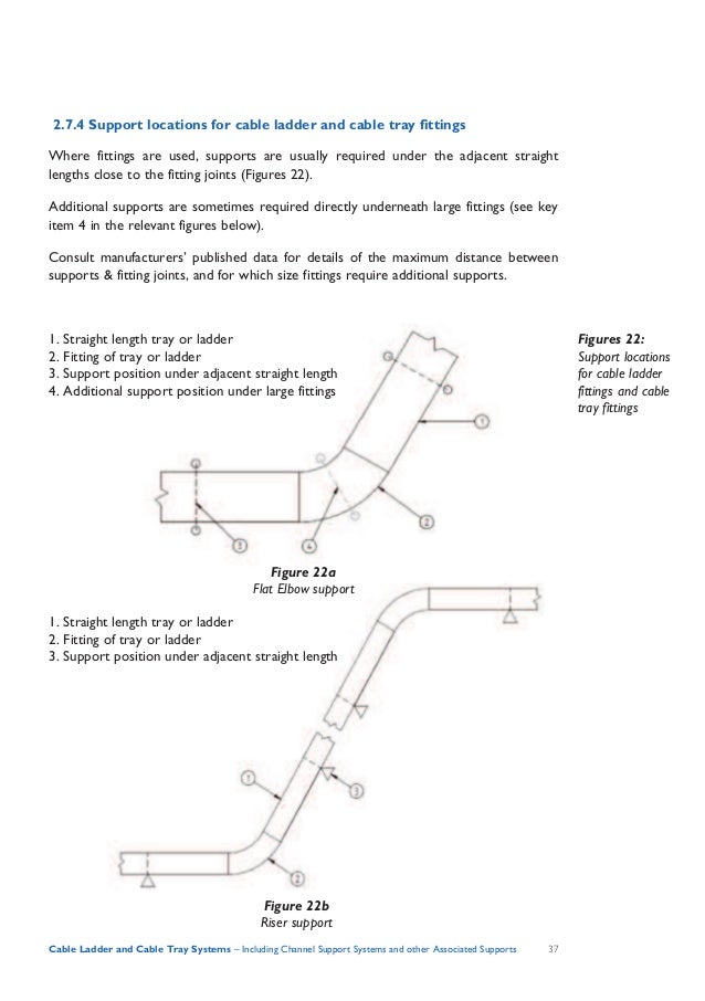
Beama Best Practice Guide To Cable Ladder Cable Tray Systems

Maybe Planks In Rafters To Support Cable Trays Or Loops Cathedral Ceiling Building A House Roof Truss Design

Method For Installation Of Cable Tray Part 1 Electrical Notes Articles

Boscam Fr632 Diversity 5 8ghz 40ch Auto Scan Lcd A V Receiver Receiver Diversity Fpv
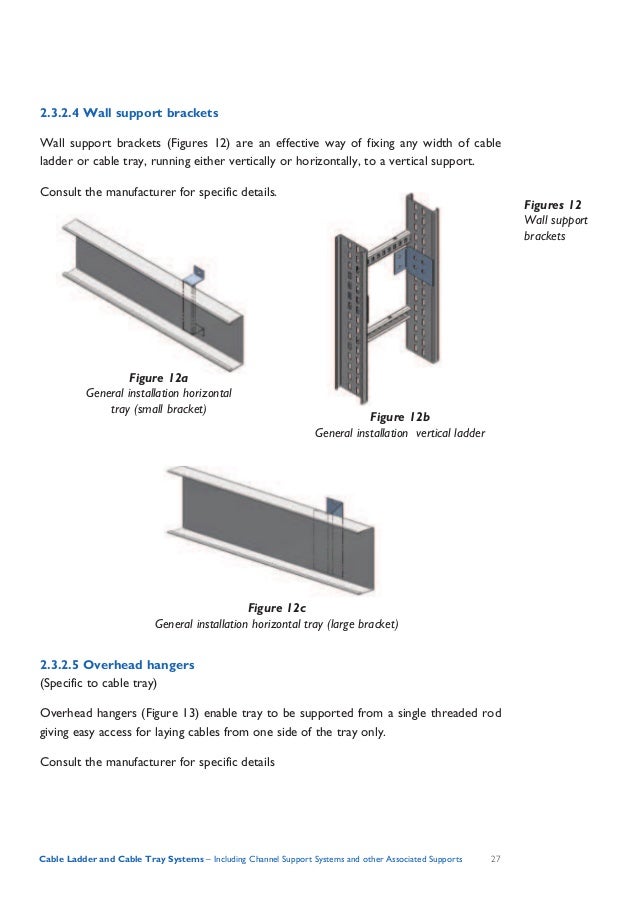
Beama Best Practice Guide To Cable Ladder Cable Tray Systems

Pin On Electrical

Method For Installation Of Cable Tray Part 1 Electrical Notes Articles

Ceiling Fan Size Guide How To Measure And Size A Fan For Any Room Ceiling Fan Size Ceiling Fan Ceiling Fan Bedroom
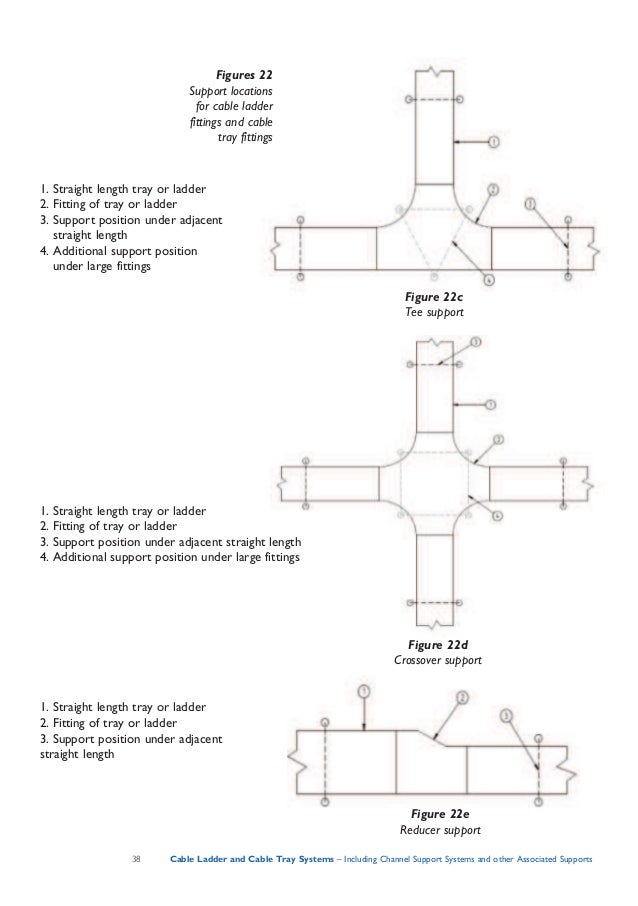
Beama Best Practice Guide To Cable Ladder Cable Tray Systems

Cable Support Systems Design And Installation Ee Publishers

Method For Installation Of Cable Tray Part 1 Electrical Notes Articles

14u Mobile Rack Adjustable Shelving Sliding Shelves Rack

Huaneng Telecom Co Ltd In China Produce And Export Preformed Line Products Fiber Optical Cable Accessories Cable Cable Tray Wire Clamp Fiber Optic Cable
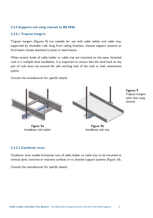
Beama Best Practice Guide To Cable Ladder Cable Tray Systems
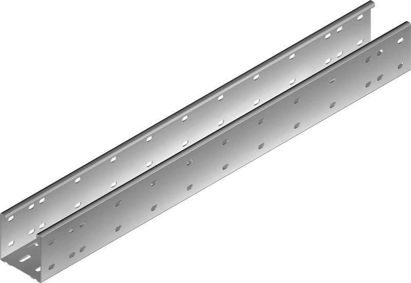
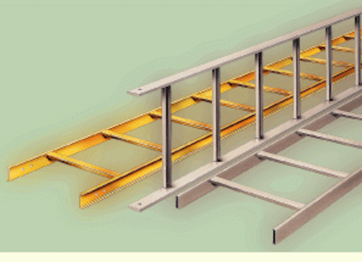
Self Supporting Trays
Http Www Sourceiex Com Catalogs Chapter 2014 20cable 20support 20systems Pdf

Method For Installation Of Cable Tray Part 1 Electrical Notes Articles

Pin On Electricians
Cable Tray Safe Working Load Test Swl Electrical Safety
0 Response to "Cable Tray Support Span Distance"
Post a Comment